|


Active dipole AD370 (Refreshed)
At
the end of October 2023, I received an email from the then unknown
hobby colleague "Thilo O." with the question of which ferrite ring
types the amplifier of the Datong AD370 could have. The number of
windings of the double and triple wires was also important to him.
As I own two of these rare active dipole amplifiers, I took Thilo
detailed photos of the amplifier board, from which the number of
windings could be clearly seen. Unfortunately, I also didn't know
the type of ferrite ring. No information on this can be found on the
Internet. So I asked a technician friend of mine which type of
ferrite ring he would recommend. The ferrite ring type "N30" should
be the right one, which turned out to be the case.
The reason for the request was that he wanted to replicate the
Datong amplifier board as accurately as possible. I was a little
surprised! The AD370 works on the principle of "transformer negative
feedback" and winding the ferrite rings is complex and not easy.
Most technicians want to avoid the "fiddling" as much as possible.
Well, one of them has taken the trouble.
Here you can find details on the functional principle of the AD370. >Link<
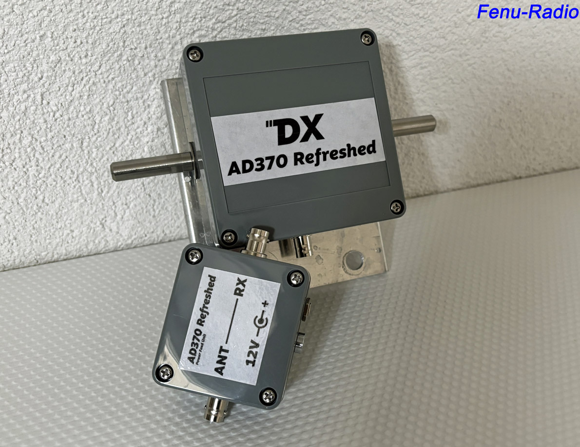
At the beginning of December 2023, I received an unexpected message
that the AD370-R was on its way to me. And it was already installed
in a housing.
This was of course very pleasing. The AD370, which was thought to be
dead, was brought back to life.
The shipment arrived here a few days later. Thilo sent me the
antenna amplifier so that I could compare it with the original AD370
amplifier. The aim was to achieve the most identical reception
behavior possible. To make this possible, I had to modify the
housing of the replica slightly. I mounted the dipole element
brackets that I had previously used for other active dipole projects
so that I could attach dipole elements of the same length. See
picture below. I also had to build the mast bracket myself. This was
as identical as possible to the original.
Bias Tee
A bias tee is required to supply the amplifier of the active
antenna with the necessary voltage. This enables the signal received
from the antenna to be forwarded to the receiver at the same time.
For this to work, an electronic circuit is included in the bias tee.
This also prevents the supply voltage from reaching the receiver.
This would be harmful to the receiver in any case. The components
must also be correctly dimensioned so that they allow the entire
frequency range that the amplifier is capable of receiving to pass
through to the receiver. And with as little interference as possible!
That was the problem with the original Datong AD370. Its bias tee
was poorly built and caused poor reception on long and medium wave.
The signal was very noisy. With a good bias tee, the AD370 received
much better.
Thilo supplied me with the bias tee a few weeks later because it was
not clear which switch circuit he should build. I can't say where
the circuit came from.
So I tried out the bias tee. Reception was fine until I focused on
the higher frequency ranges. Between 20 and 30MHz I noticed
increased noise in reception. A comparison with the original AD370
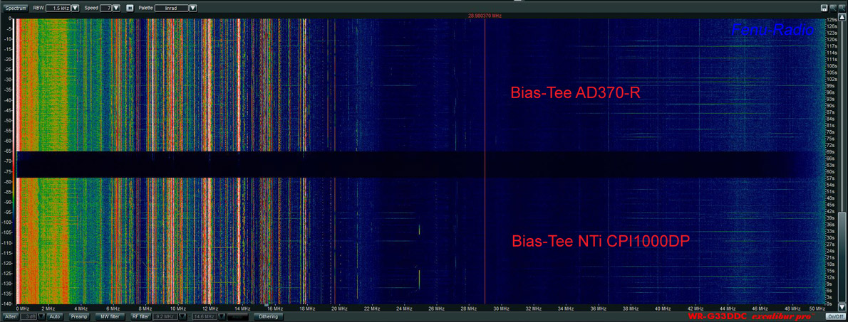
showed the difference in the broadband spectrum. Two thick noise
bells could be seen in the spectrum, approx. 15dB above the normal
noise floor. Something could not be right! I unscrewed the bias tee
to check whether there was a bad solder joint somewhere. It wasn't.
Reconnected and on reception, I wrapped a large piece of aluminum
foil around bias tee. Lo and behold! The noise between 20-30MHz had
disappeared. So there must be something wrong with the crossover! I
then removed the circuit board and took a closer look.
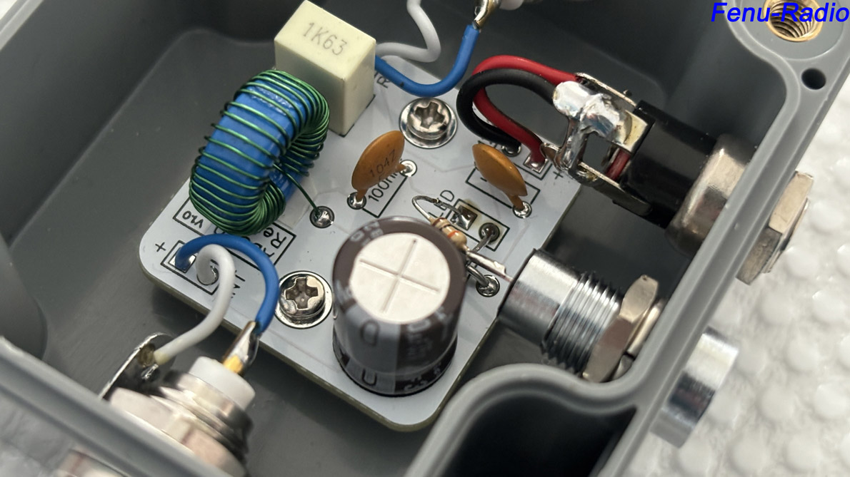
It turned out that the V1.0 board had no ground plane. If you held
it in front of a bright lamp, the light shone through the board.
Only the conductor tracks were visible. The conductor tracks on the
board were also very thin, which was not ideal. So there were two
faults in the circuit board. Thilo was informed of this, whereupon
he set about building a bias tee. The new board V2.1 was here after
a short time. The dimensions of the new board were the same and it
could be installed in the same housing. It worked a little better,
but unfortunately still not completely clean. The noise humps were
now above 29MHz and no longer in the middle of the shortwave. The
bias tee also reacted to nearby metal. So not yet satisfactory.
I carried out the comparison test with a different bias tee, because
the AD370-R amplifier works cleanly. The CPI1000DP remote bias tee
from Bonito was used for this. It works perfectly.
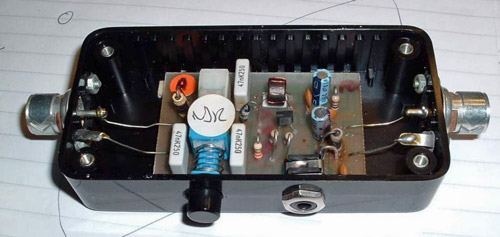
Picture 1: Defective bias tee V1.0 of
AD370-R (white board)
Picture 2: Corrected bias tee V2.1 of AD370-R
(green board)
Original bias tee of the Datong AD370.
A faulty design that extremely limited the reception performance of
the AD370.
The AD370 Original / AD370-R
amplifiers
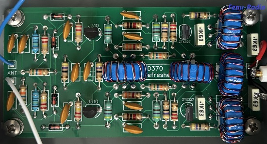
The comparison! If you look at the two amplifiers, you can't say
that they look the same. Where you can see a certain similarity is
in the hand-wound ferrite rings. Both boards have 5 of each. The
important thing is that the electrical values and the reception
behavior are the same. A quick test of the AD370-R did not reveal
any defects. Now we can move on to the actual comparison test.
|
Datong AD370
original amplifier board
Year of manufacture around 1990
 |
Datong AD370-R amplifier board (replica)
Year of manufacture 2023
 |
The comparison
To carry out a comparative test, the two antennas must be offered
the same conditions as far as possible.
I mounted the candidates on the same glass fiber mast. Beforehand, I
checked whether the antennas interfered with each other. This was
not the case.
Test conditions
-AD370-R mounting height: 5.5m
-Height of AD370 Original: 4.9m
-Length of the dipole elements for both antennas: 2x1.25m
-Bias Tee AD 370-R: Bonito CPI1000DP (the supplied did not work
properly at the time of testing)
-AD370 Original bias tee: Bonito CPI1000DP (the original is no good)
-Belden H155 coaxial cable for both antennas
-Winradio G33DDC Excalibur Pro receiver
-Elad FDM-S3 receiver
-Antenna switch: Elad ASA-62 & passive antenna switch

It became clear
relatively quickly which direction the comparison test would take.
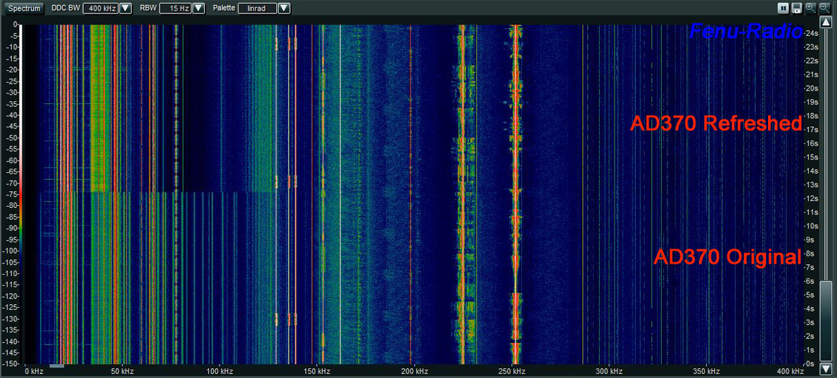
The two antennas differed minimally from each other. In the VLF
range, both antennas receive equally well. Differences are only
noticeable when picking up local interference. The AD370-R is less
susceptible to this in the 0-200KHz range. As the frequency
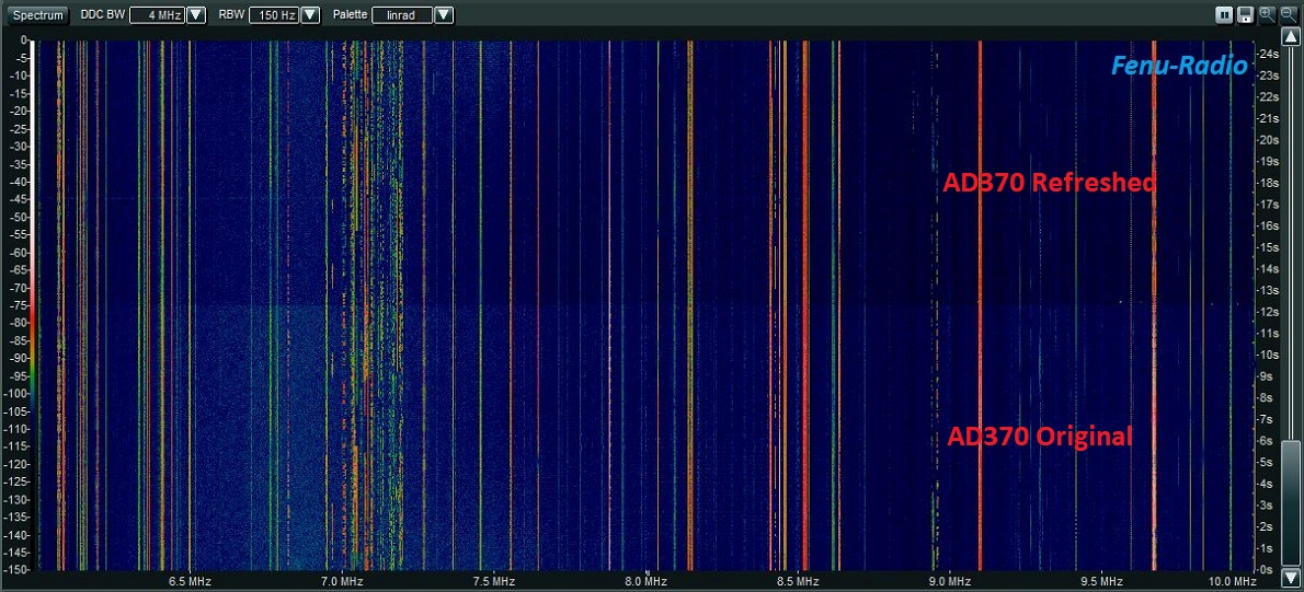
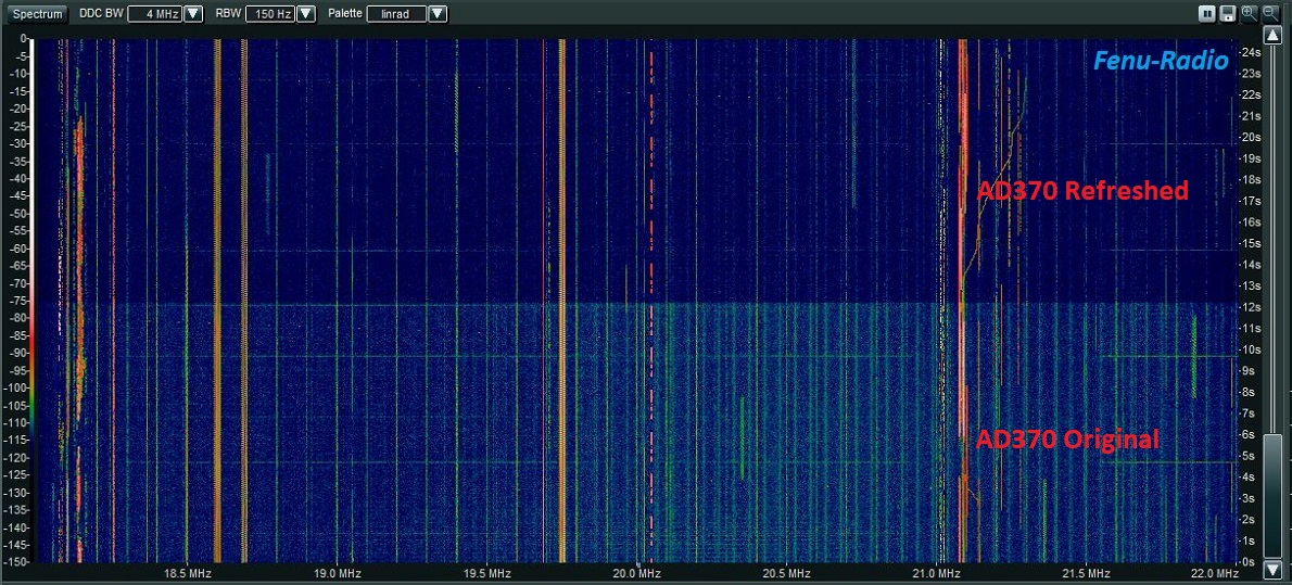
increases, you can see from the waterfall diagrams that the AD370-R
has slightly less background noise in comparison and is also less
susceptible to local interference. The darker the blue, the lower
the noise floor. This can be seen in the 0-30MHz waterfall diagram.
The gain of the two antennas is very close to each other. The
AD370-R has approx. 3dB less level in the upper frequency ranges.
This is only noticeable with the weakest stations in the 11/10m
band.
Waterfall diagram
0-30MHz

The waterfall diagram above
shows the frequency range 0-30MHz with 1.5KHz resolution. Click on
it to open a new browser window. The JPG file is over 70MB in size
and takes a few seconds to load. The waterfall diagram is then
greatly enlarged. So you can see every detail. I recommend that you
only open this file with a fast internet connection.
Waterfall diagrams
0-200KHz - 0-2MHz - 2-6MHz
Waterfall diagrams
6-10MHz - 10-14MHz - 14-18MHz
Waterfall diagrams
18-22MHz - 22-26MHz - 26-30MHz
Large signal
behavior
This is always a big topic, the large signal behavior! How does the
AD370-R cope with strong signals?
I have known the AD370 Original for years. It is my reference
antenna. That doesn't mean it's perfect. Because it also reaches its
limits from time to time. With signals from S9+35dBm it starts to
generate intermodulation. So far, these have always been signals at
twice the transmitter frequency. Transmitter mixtures were rarely
heard. Then there must have been a few very strong transmitters
mixing on various frequencies.
I have only known the AD370-R since the beginning of 2024. I was
looking for intermodulation almost every evening. And I found them!
They are practically the same as the AD370 Original. Here, too, the
antennas hardly differ from each other. There were no transmitter
mixes due to a lack of very strong signals.
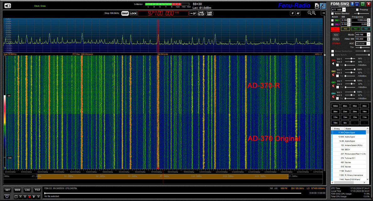
Reception above 30MHz
According to the technical data, the AD370 Original receives up to
100MHz. The AD370-R can keep up. The FM broadcast band could be
received in almost the same quality with both antennas. The AD370-R
is somewhat noisier in this range. This is due to the bias tee. This
19MHz wide waterfall diagram was made with the Elad-S3.
Source of supply
for the AD370-R
For further information
titus.oxx@gmail.com
Conclusion
Thilo has managed to breathe new life into the old Datong AD370! The
AD370-R works almost as well as the original. Apart from non-tragic
details such as slightly less level in the upper HF ranges. There is
still one problem. The bias tee still has faults even after the
update. It causes a noise bell above 29MHz. It also reacts to
metallic surfaces in the vicinity. I am sure that this error will be
corrected.
Otherwise, the AD370-R is a worthy successor to the old Datong
AD370.
posted: 17.03.2024
Aktivdipol AD370-R update
After a few months of operating experience and feedback to the
manufacturer, the following changes were made to the amplifier and
the remote power supply.
Cooling elements were fitted to two transistors to better dissipate
the heat generated.

The bias tee was rebuilt and installed in a cast aluminum
housing. It now works perfectly.
posted: 21.07.2024


|


.jpg)
.jpg)


